4-12 Inch A-USP1 RWGV SLxFL

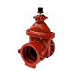
4-12 Inch A-USP1 RWGV SLxFL
Catalog numbers:
- A-USP1-41 Slip-on† end (with gasket) x flange end
- A-USP1-43 Slip-on† end (less gasket) x flange end
Specifications:
- Sizes – 4", 6", 8", 10", 12"
- Meets or exceeds all applicable requirements of ANSI/AWWA C515 Standard, UL 262 Listed, FM 1120/1130 Approved, and certified to ANSI/NSF 61 & 372.
- Slip-on ends fit plain end of classes 150, 200 and 250 cast iron, ductile iron and classes 150 and 200 cast iron O.D. PVC
- Flange end drilling complies with ASME/ANSI B16.1 Class 125
- Iron body with nominal 10 mils Pro-Gard® Fusion Bonded Epoxy Coated interior and exterior surfaces
- Epoxy coating meets or exceeds all applicable requirements of ANSI/AWWA C550 Standard.
- Iron wedge, symmetrical & fully encapsulated with molded rubber; no exposed iron
- Non-rising stem (NRS)
- Triple O-ring seal stuffing box (2 above the thrust collar and 1 below)
- 2" square wrench nut – open left or open right
- 300 psig (2000 kPa/20 barg) maximum working pressure, 600 psig (4100 kPa/ 41 barg) static test pressure
- UL Listed, FM Approved: 300 psig (2000 kPa/20 barg)
- Designed for potable water applications
††Field Lok is a trademark of U.S. Pipe and Foundry Company, used with permission.
Options*:
- Position indicators
- Stainless steel stem: Type 304, Type 316
- Low zinc, silicon bronze ASTM B98-C66100/H02 stem
- Handwheel
- EPDM Disc and O-rings
RESOURCES:

Dimension | Nominal Size | ||||
4" | 6" | 8" | 10" | 12" | |
A | 14.19 | 18.00 | 21.50 | 25.50 | 28.62 |
Q (bore) | 4.30 | 6.30 | 8.30 | 10.30 | 12.30 |
L | 4.12 | 4.38 | 5.62 | 5.62 | 5.62 |
R | 9.00 | 11.00 | 13.50 | 16.00 | 19.00 |
UU (bolt circle diameter for FL) | 7.50 | 9.50 | 11.75 | 14.25 | 17.00 |
B (number and size of holes for FL) | 8--.75 | 8--.88 | 8--.88 | 12--1.00 | 12--1.00 |
W (distance between strapping lug holes across face of valve ends) | 8.62 | 10.62 | 13.12 | 16.38 | 18.12 |
FF | 10.91 | 12.73 | 14.72 | 15.75 | 16.35 |
Turns to open | 14 | 20.5 | 26.5 | 33 | 38.5 |
Weight* | 93 | 140 | 241 | 368 | 523 |

Catalog Part No. | Description | Material | Material Standard |
G-16 | Bonnet Bolts & Nuts | 316 Stainless Steel | ASTM F593 (bolt) ASTM F594 (nut) |
G-41 | Stuffing Box Bolts & Nuts | 316 Stainless Steel | ASTM F593 (bolt) ASTM F594 (nut) |
G-49 | Stem O-rings (3) | Nitrile | ASTM D2000 |
G-200 | Wrench Nut Cap Screw | 316 Stainless Steel | ASTM F593 |
G-201 | Stuffing Box O-ring | Nitrile | ASTM D2000 |
G-202 | Wrench Nut | Ductile Iron | ASTM A536 ▼ |
G-203 | Stem | Bronze | ASTM B138 |
G-204 | Hand Wheel (not shown) | Cast Iron | ASTM A126 CL.B |
G-205 | Stem Nut | Bronze | ASTM B584 |
G-206 | Guide Cap Bearings | Acetal | - |
G-207 | Stuffing Box with dirt seal | Ductile Iron Nitrile | ASTM A536 ▼ ASTM D2000 |
G-208 | Anti-friction Washers (2) | Acetal | - |
G-209 | Wedge, Rubber Encapsulation | Ductile Iron* SBR | ASTM A536 ▼ ASTM D2000 |
G-210 | Bonnet | Ductile Iron | ASTM A536 ▼ |
G-211 | Bonnet O-ring | Nitrile | ASTM D2000 |
G-212 | Body | Ductile Iron | ASTM A536 ▼ |
▼ Material strength ASTM A536 65-45 minimum
** Per ANSI/AWWA C111 working pressure above 250psi requires the use of a special gasket rated for higher pressure.